For UK enquiries please visit polymax.co.uk or contact us on 01420 474123 | Email [email protected]
+44 (0) 1420 474123
£ GBP
£ British Pound Sterling (GBP)
Change currency:
  • € Euro (EUR)
  • Rs Indian Rupee (INR)
  • zł Polish Zloty (PLN)
  • $ US Dollar (USD)

[email protected]
You have no items in your shopping cart.
0
Cart

Monthly Archives: June 2026

  • How to Specify and Select the Right Anti Vibration Mounts


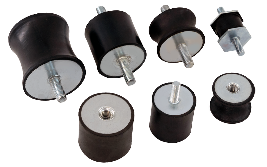
    Anti vibration mounts, also known as AV mounts or vibration isolators, are rubber or elastomeric components used to absorb and dampen mechanical vibrations and shocks. They help prevent damage, reduce noise, and improve operator comfort in various mechanical systems. Whether you are working in industrial automation, HVAC systems, automotive applications, or marine environments, choosing the correct anti vibration mount can significantly extend the lifespan of your equipment and enhance overall performance.

    Before beginning the selection process, it is important to clearly understand the specific objectives you want to achieve with the anti vibration mount, whether that’s reducing noise, protecting sensitive equipment, minimising shock loads, or improving operator comfort. This understanding will guide your choices and help you specify the most effective mount for your application.

    To ensure optimum performance, it’s essential to know the criteria for specifying and selecting anti vibration mounts, how often they should be inspected, and when they should be replaced.

    Criteria for Specifying Anti Vibration Mounts

    When selecting anti vibration mounts, consider the following criteria carefully:

    1. Load Requirements

    Each mount is designed to support a specific static and dynamic load. Overloading can cause premature failure, while under-loading may reduce isolation effectiveness. Consider the following:

    • Determine the equipment weight.
    • Distribute weight evenly across mounts.
    • Factor in dynamic forces (e.g., from motors or compressors).

    2. Vibration Frequency

    Vibration frequency is one of the most important factors when selecting an anti vibration mount. It refers to how quickly a machine vibrates and is typically measured in Hertz (Hz), or cycles per second.

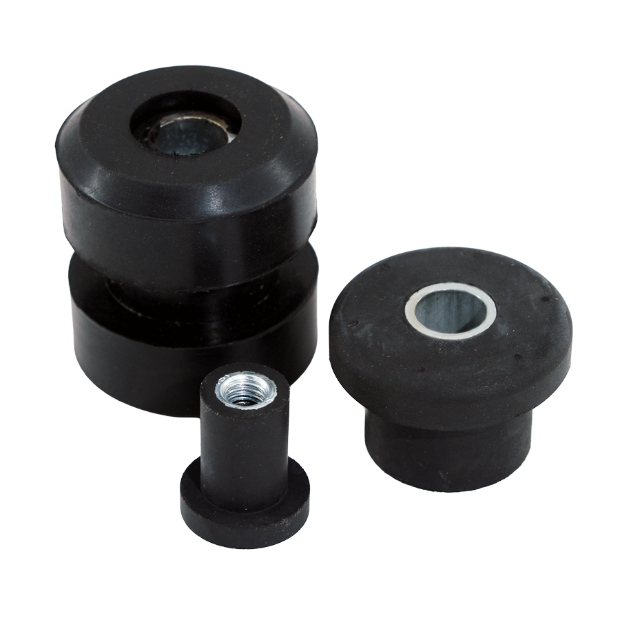
    Every piece of rotating equipment generates vibration at a specific frequency based on its operating speed. For example:Centre Bonded Bush Anti-Vibration Mounts
    • A motor running at 1,800 RPM produces a vibration frequency of 30 Hz.
    • A compressor operating at 3,600 RPM produces a vibration frequency of 60 Hz.

    To convert RPM to Hertz, use the following formula:

    Frequency (Hz) = RPM ÷ 60

    For anti vibration mounts to isolate vibration effectively, their natural frequency must be significantly lower than the vibration frequency of the equipment. This creates an isolation zone where vibration energy is absorbed rather than transmitted to surrounding structures.

    If the equipment's vibration frequency is too close to the mount's natural frequency, resonance can occur. Resonance amplifies vibration, increasing noise levels, accelerating component wear, and potentially causing equipment damage.

    As a general rule, the operating vibration frequency should be at least 1.4 to 2 times greater than the mount's natural frequency to achieve effective vibration isolation.

    When selecting a mount, also consider the relationship between load and stiffness:

    • Stiffer mounts have a higher natural frequency and provide less vibration isolation.
    • Softer mounts generally offer better vibration isolation but may allow greater movement.
    • Heavier loads compress mounts further, reducing their natural frequency and improving low-frequency isolation.

    For optimum performance, always select a mount that supports the equipment load while maintaining a natural frequency well below the machine's operating frequency.

    2.1 Understanding Static Deflection

    Static deflection is the amount a mount compresses under a given static load. It is one of the most critical parameters for determining the natural frequency of a mount and, therefore, its vibration isolation performance. In general, the greater the static deflection, the lower the mount’s natural frequency and the better its ability to isolate low-frequency vibrations.

    As a rule of thumb:

    • Higher static deflection = better isolation, but may allow more movement or sway.
    • Lower static deflection = stiffer support, better for high-frequency or precise applications.
    Polymax provide static deflection data (e.g., mm per kg or inches per pound), which helps you compare mounts and ensure their deflection fits your equipment’s isolation and stability requirements.

    When selecting a mount:

    • Estimate the deflection based on your equipment’s weight.
    • Check that the deflection is within the optimal operating range of the mount.
    • Avoid over-compressing (which can bottom out the mount) or under-loading (which reduces vibration damping).

    3. Environmental Conditions

    The working environment can affect the longevity and performance of mounts. Consider:

    • Temperature ranges.
    • Exposure to oil, chemicals, UV, or moisture.
    • Outdoor vs. indoor use.

    Select materials like neoprene, EPDM, or natural rubber depending on these factors.

    4. Mount Orientation and Movement

    Mount orientation refers to the direction and type of forces the anti vibration mount must handle typically axial (vertical), radial (horizontal), or multi-directional loads. It is essential to choose a mount that is specifically designed to withstand the dominant direction of force in your application.

    Mount Type Typical Features / Use Axial Loads (Vertical) Radial Loads (Horizontal) Multi-Directional Loads Typical Applications
    Bobbin Mounts Compact, simple, cost-effective ★★★★★ ★★☆☆☆ ★☆☆☆☆ Motors, pumps, fans, light machinery
    Anti-Vibration Pads Levelling, shock isolation, low profile ★★★☆☆ ★★☆☆☆ ★★☆☆☆ HVAC units, enclosures, cabinets
    Shear Compression Mounts High load capacity, excellent stability ★★★★☆ ★★★★☆ ★★★☆☆ Compressors, engines, industrial machinery
    Machinery Feet Levelling and vibration isolation ★★★★☆ ★★★☆☆ ★★☆☆☆ Machine tools, presses, heavy equipment
    High Deflection Mounts Low-frequency vibration isolation ★★★☆☆ ★★★☆☆ ★★★★☆ Sensitive equipment, test rigs
    Buffers and Stops Impact absorption, end-of-travel protection ★★★★★ ★☆☆☆☆ ★☆☆☆☆ Doors, conveyors, cranes
    Generator Mounts Designed for gensets and power units ★★★★☆ ★★★☆☆ ★★★☆☆ Generators, alternators
    Cylindrical Bushes Simple, durable radial compliance ★☆☆☆☆ ★★★★☆ ★★☆☆☆ Linkages, pivots, control arms
    Centre Bonded Bush Metal bonded, high shear strength ★★★☆☆ ★★★★☆ ★★★☆☆ Automotive and industrial linkages
    Vehicle Suspension Mounts Road shock and vibration isolation ★★★☆☆ ★★★☆☆ ★★★★☆ Cars, trucks, off-road vehicles
    Marine Mounts Corrosion resistant, high isolation ★★★★☆ ★★★★☆ ★★★★★ Marine engines, gearboxes, vessels
    Sandwich Mounts Strong, stable, good shear resistance ★★★★☆ ★★★★★ ★★★☆☆ HVAC, pumps, compressors
    Cone Transit Mounts Shock absorption, transport protection ★★★★☆ ★★★★☆ ★★★★★ Marine, military, rail, generators


    Incorrect orientation can lead to premature failure, poor vibration damping, or even damage to connected machinery, so always match the mount’s design to the load direction for optimal performance and longevity.

    Consider the direction of forces:

    • Axial (vertical loads)
    • Radial (horizontal loads)
    • Multi-directional motion

    5. Durability and Life Expectancy

    Choose mounts rated for long-term performance and resistance to fatigue. 

    How Often Should Anti Vibration Mounts Be Checked?

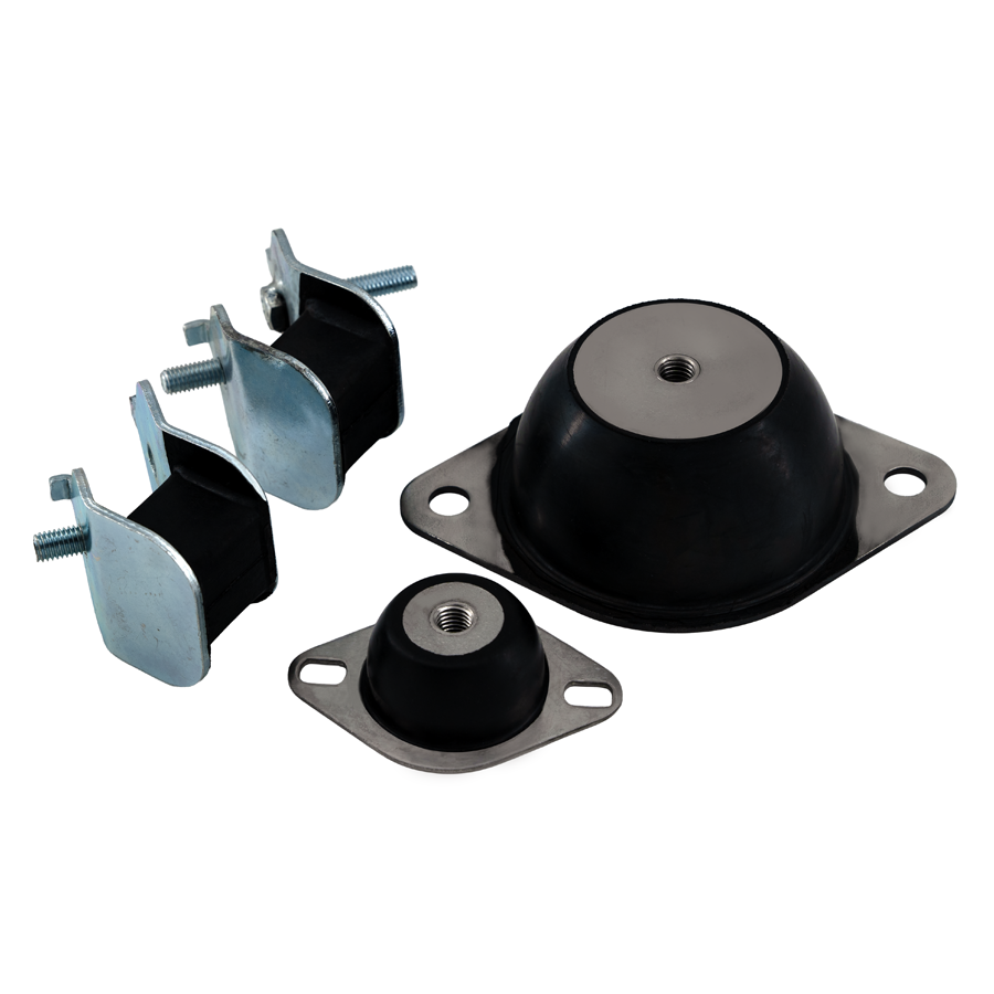
    To ensure a long operating life and maintain optimal vibration isolation, regular inspections are critical. We recommend the following inspection frequencies:Anti-Vibration Mount
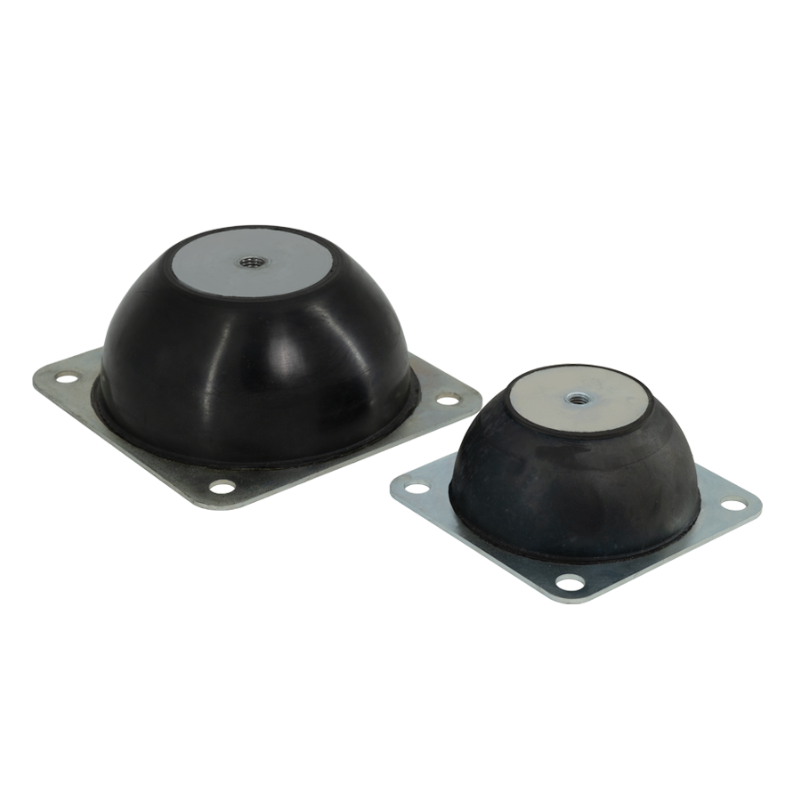
    • Every 6–12 months for standard industrial applications.
    • Quarterly inspections in high-vibration or mission-critical environments.
    • After any major equipment movement, repair, or shock event.

    What to check during inspections:

    • Cracks, splits, or hardening in rubber components.
    • Loosening of mounts or hardware.
    • Excessive compression or deformation.
    • Rust or corrosion on metal parts.

    When Should Anti Vibration Mounts Be Replaced?

    Even the best anti vibration mounts degrade over time. Common signs that mounts need to be replaced include:

    • Loss of vibration isolation.
    • Increased noise or rattling.
    • Visible wear or deterioration.
    • Mounts have reached their expected service life (usually 3–7 years, depending on application and material).

    Always replace mounts in sets to maintain balance and even load distribution.

    Selecting the correct anti vibration mount is essential for reducing noise, controlling vibration, protecting equipment, and extending service life. By carefully considering load requirements, vibration frequency, static deflection, environmental conditions, and mounting orientation, you can ensure reliable performance and effective vibration isolation.

    Regular inspection and maintenance are equally important. Monitoring mounts for signs of wear, deformation, corrosion, or loss of isolation performance can help prevent costly downtime and unexpected equipment failures.

    For expert advice and product recommendations tailored to your needs, contact our team of experts on +44 (0) 1420 474 123 or E-mail us. 

  • Oil, Gas, Offshore & Subsea O-Ring Standards Explained: NORSOK M-710, M-711, AED/RGD & NACE

    In the oil, gas, offshore, and subsea industries, O-rings may be small components, but they perform a critical role in maintaining the integrity of high-value equipment. These elastomer seals operate in some of the world's harshest environments, where they are exposed to extreme and fluctuating pressures, wide temperature ranges, aggressive hydrocarbons, chemical injection fluids, and sour gas containing hydrogen sulphide (H₂S).

    Failure of a single O-ring can lead to loss of containment, unplanned downtime, environmental incidents, costly repairs, and serious safety risks. As a result, operators and equipment manufacturers rely on internationally recognised standards and material qualification programmes to ensure sealing reliability throughout the life of an asset.

    Understanding offshore O-ring standards and certification requirements is essential for engineers, procurement professionals, maintenance teams, and project managers responsible for specifying sealing solutions in demanding oil and gas applications.

    Why O-Ring Certification Matters in Offshore and Subsea Environments

    Offshore and subsea equipment places significant demands on elastomer materials. Certified O-rings provide confidence that the seal material has been tested and qualified to perform under the conditions it will encounter in service.

    Using qualified sealing materials helps ensure:

    • Reliable sealing under high pressures and challenging temperatures
    • Resistance to sour gas (H₂S), hydrocarbons, and aggressive chemicals
    • Compliance with operator, project, and regulatory requirements
    • Consistent manufacturing quality and material traceability
    • Reduced maintenance costs and lower lifecycle risk

    Ensuring you use certified O-rings is a risk management strategy, not just a regulatory requirement.

    NORSOK Standards: M-710 & M-711 for Offshore Elastomers

    Developed by the Norwegian petroleum industry, NORSOK standards were created to improve safety, reliability, and cost efficiency across the Norwegian Continental Shelf. Today, NORSOK standards are widely specified throughout global offshore and subsea projects and are often regarded as the benchmark for elastomer qualification.

    While NORSOK compliance is not legally required outside Norway, many operators and equipment manufacturers specify NORSOK-qualified materials as part of their technical requirements. In practice, this can make compliance essential for participation in offshore projects worldwide.

    It is important to understand that NORSOK standards qualify elastomer compounds rather than individual O-rings. To maintain compliance, manufacturers must produce seals using approved formulations, controlled manufacturing processes, and full batch traceability.

    Key Points:

    • NORSOK is not legally required outside Norway, but operators often treat it as mandatory.
    • NORSOK standards focus on compound qualification, not individual O-rings.
    • Approved elastomer compounds must be manufactured with controlled processes and full traceability to maintain compliance.

    Scope of NORSOK Elastomer Standards


    Standard Primary Focus Relevance to O-Rings
    M-710 Qualification testing of non-metallic sealing materials Defines thermal ageing, chemical resistance, and RGD testing
    M-711 Material requirements for elastomers Sets property limits, mechanical performance, and manufacturing traceability


    NORSOK M-710 remains one of the most widely specified qualification standards for elastomer materials used in offshore and subsea sealing applications, particularly where long-term reliability is critical.

    Global Use of Offshore Elastomer Standards

    While NORSOK standards originated in Norway, offshore operators worldwide often specify a combination of NORSOK, NACE, API, and ISO requirements depending on project location and operating conditions.

    Region Commonly Specified Standards Why It Matters
    Norway / North Sea NORSOK M-710 / M-711, NACE Often contractually mandatory for offshore projects
    UK North Sea NORSOK, NACE, ISO Ensures equipment acceptance by multiple operators
    Middle East NACE, operator-specific Focus on sour service and chemical resistance
    Gulf of Mexico NACE, API, ISO Meets regulatory and operator requirements
    Asia-Pacific Offshore NORSOK (subsea), ISO, NACE Demonstrates offshore reliability for subsea projects

    Understanding which standards apply to a project is a crucial part of selecting suitable offshore O-rings and sealing materials.

    AED & RGD Testing for High-Pressure Elastomers

    One of the most important considerations for offshore and subsea elastomers is resistance to rapid gas decompression (RGD), sometimes referred to as explosive decompression.

    When an elastomer is exposed to high-pressure gas, molecules can permeate into the material. If pressure is released too quickly, the trapped gas expands faster than it can escape, causing internal cracking, blistering, or catastrophic seal damage.

    Term Description
    AED (Anti-Explosive Decompression) Ability of elastomer to resist damage from rapid decompression under high pressure
    RGD (Rapid Gas Decompression) Physical phenomenon tested to evaluate elastomer resistance to explosive decompression

    AED/RGD resistance is particularly important in:

    • High-pressure valves
    • Subsea connectors
    • Production manifolds
    • Gas compressors
    • Blowout preventers (BOPs)
    • Downhole completion tools

    Because pressure cycling is unavoidable in these applications, AED/RGD-qualified O-rings are often considered essential for long-term reliability.

    NACE TM0187 for Sour Service

    Hydrogen sulphide (H₂S) presents one of the most aggressive environments encountered in oil and gas production. Exposure to sour gas can accelerate elastomer degradation, resulting in swelling, embrittlement, cracking, and premature seal failure.

    NACE TM0187, provides internationally recognised guidance for material selection in H₂S-containing environments. Compliance helps ensure sealing materials maintain their performance and integrity throughout service life.

    Typical Applications Requiring NACE Compliance

    While NORSOK focuses on overall offshore elastomer qualification, NACE specifically addresses material performance in sour service environments.

    Application Type NACE MR0175 Requirement Why This Matters
    Sour Gas Production Mandatory Prevents H₂S-induced seal failure
    Sour Oil Production Mandatory Ensures long-term integrity
    Gas Processing Mandatory Maintains chemical compatibility
    Sweet Service Not Required Standard elastomers acceptable


    O-Ring Material Selection and Certification

    Selecting the correct O-ring material involves far more than choosing a polymer family. Performance depends on the complete compound formulation, including fillers, curing systems, and manufacturing controls.

    As a result, generic material descriptions alone are insufficient when specifying O-rings for offshore, subsea, or sour service applications.

    Elastomer Materials Availability. 

    For demanding offshore applications, HNBR, FKM, and FFKM compounds are among the most frequently specified materials due to their ability to satisfy multiple qualification requirements simultaneously.

    Material NORSOK AED / RGD NACE Typical Use Notes
    HNBR Oil & gas, sour service Widely used in high-pressure sour applications
    FKM (VitonFile:RegisteredTM.svg) High-temp hydrocarbons Select compound grades only
    Aflas Sour gas wells, high-pressure gas systems, chemical injection systems Excellent resistance to H₂S
    FFKM Extreme chemicals & temperature Often used in critical subsea applications

    Only compounds that have passed recognised tests, should be used for these applications, contact Polymax to ensure you are selecting a certified compound.

    Choosing the Right O-Rings

    When specifying O-rings for offshore, subsea, and sour service environments, it is important to evaluate both the application conditions and the certification requirements.

    Before selecting a sealing material, consider:

    • Required standards and project specifications, including NORSOK M-710, M-711, NACE TM0187, & TM0297.
    • Operating pressures and temperature ranges
    • Exposure to hydrocarbons, production chemicals, and sour gas
    • AED/RGD resistance requirements
    • Material certification and traceability documentation
    • Long-term reliability and maintenance considerations

    Selecting the correct offshore O-ring requires more than matching material types. Certification status, pressure profile, temperature range, chemical exposure, and sour service requirements all influence sealing performance and operational reliability.

    Our technical team can help identify compliant NORSOK, AED/RGD-resistant, and NACE-compliant O-ring solutions for your application. Contact us on +44 (0) 1420 474 123 or email us for expert technical guidance.

    File:RegisteredTM.svg File:RegisteredTM.svg
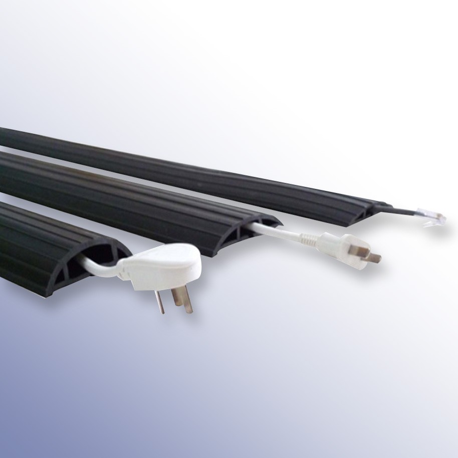
  • How to Choose the Right Cable and Hose Protectors


    Protecting people should always be the first priority, whether in a warehouse, on a construction site or at a temporary event. Exposed cables and hoses can quickly become trip hazards, putting employees, contractors and members of the public at risk of injury. In areas where vehicles operate, unprotected cables can also become damaged, leading to equipment failure, costly downtime and additional safety concerns. 

    Choosing the right cable or hose protector is therefore about far more than protecting cables, it is about creating safer environments, reducing risk and ensuring the smooth operation on your site.

    Why Are Cable and Hose Protectors Important?

    Slips, trips and falls remain one of the most common causes of workplace injuries across the UK. Cables and hoses running across walkways, access routes and vehicle routes present a significant risk if they are not properly managed.

    A suitable cable protector can help:

    • Protect people from slip and trip hazards
    • Protect power cables and hoses from damage
    • Improve site safety and housekeeping
    • Maintain safe access routes
    • Reduce downtime and costly repairs
    • Ensure compliance with health and safety requirements

    For temporary installations such as festivals, exhibitions, sporting events and outdoor events, cable protectors also help create safe public spaces where large numbers of people may be moving around unfamiliar environments.

    Understanding Your Legal Responsibilities

    Employers and site managers have a legal duty to assess and control workplace risks.

    Relevant legislation and guidance may include:

    Failure to adequately manage cables and hoses can result in accidents, enforcement action, claims, project delays and reputational damage.

    Step 1: Consider the Environment

    The first question to ask is where the cable protector will be used.

    Environment Typical Applications Key Requirements
    Indoor Offices, warehouses, schools, exhibition halls and retail environments Low-profile covers that minimise trip hazards and allow safe pedestrian access
    Outdoor Construction sites, infrastructure projects, festivals and public events Weather resistance, durability, UV protection and suitability for uneven ground. Must withstand rain, mud, temperature fluctuations and, where necessary, heavy vehicle traffic.


    Step 2: Understand the Traffic Crossing the Protector

    One of the most important factors when choosing a cable protector is determining what will pass over it. Selecting an underspecified protector can lead to structural failure, resulting in the load being directly applied to the live cables or pressurised hoses and creating serious safety risks.

    Traffic Type Typical Applications Recommended Solution Typical Load Requirement
    Pedestrian Traffic Offices, exhibitions, festivals and public events Foot Traffic Cable Cover Pedestrians and light trolleys
    Light Vehicles Cars, service vehicles and delivery vans MCP Multi Cable Protector Light commercial traffic
    Heavy Commercial Traffic Forklifts, warehouse vehicles and plant machinery Polyurethane MPC Cable Protector Up to 40 tonnes depending on model
    Heavy Goods Vehicles Construction sites, utilities and infrastructure projects HGV Outdoor Cable Protector Up to 80 tonnes depending on model

    It is always recommended to choose a cable protector with a load rating that exceeds your expected traffic requirements. Underestimating vehicle loads is one of the most common causes of cable protector failure.

    Step 3: Consider How Long the Installation Will Be in Place

    The duration of the installation often determines the most suitable type of cable protector.

    Installation Type Typical Applications Recommended Features
    Temporary Installations Festivals, concerts, sporting events, exhibitions, film productions and emergency response situations Quick deployment, modular design, high visibility and easy repositioning
    Long-Term Installations Warehouses, manufacturing facilities, loading bays and utility installations Heavy-duty construction, high load capacity and long-term durability

    Temporary cable management is particularly important at events where large numbers of visitors may be walking across power cables, lighting cables, data lines and water hoses. In these environments, cable protectors help maintain safe access routes while protecting essential services.

    Step 4: Determine the Number and Size of Cable or Hoses

    Not all hoses carry the same materials, and the consequences of damage can vary significantly. When selecting a hose protector, consider both the hose itself and the medium being transported.

    Medium Potential Risk if Damaged Additional Considerations
    Chilled water or glycol Slips, loss of cooling, equipment damage Consider heavier-duty protection and leak response procedures
    Compressed air Hose whip, loss of service Protect against impact and crushing
    Hydraulic oil Slips and environmental contamination Robust protection and spill management
    Chemicals Injury and environmental risks Review COSHH requirements and risk assessments
    Hot water or steam Burns and scalding Protect against rupture and accidental contact

    For example, temporary chillers used during shutdowns or emergency cooling projects often require both power cables and glycol hoses to cross vehicle routes. In these situations, selecting a protector solely based on traffic loading may not be sufficient. The potential consequences of a damaged hose should also influence the level of protection chosen.

    Step 5: Consider Visibility and Access Route Clearance

    Cable protectors should improve safety, not create new hazards.

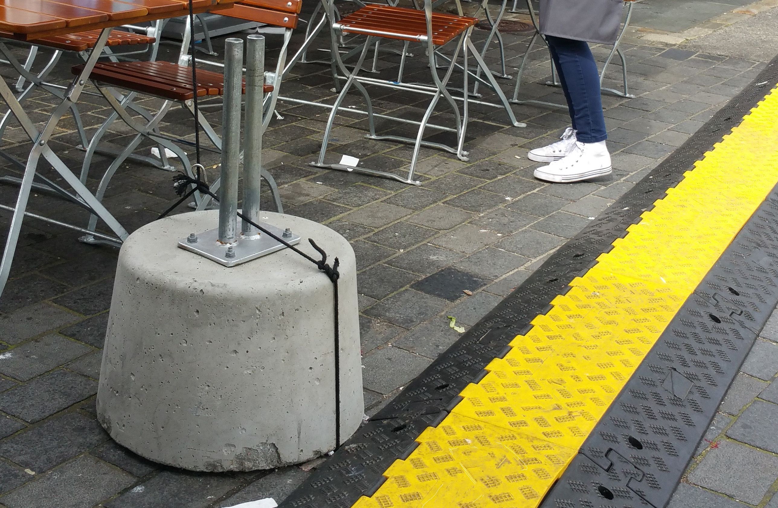
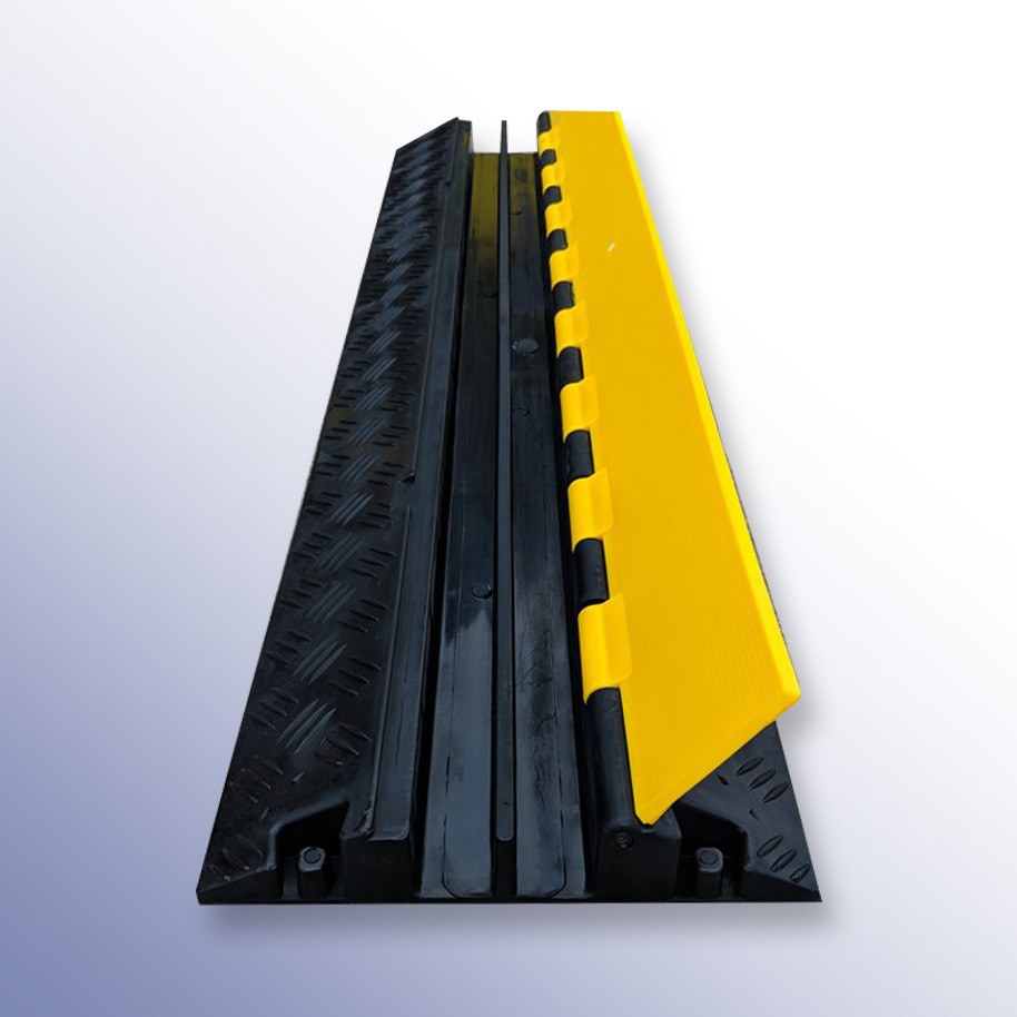
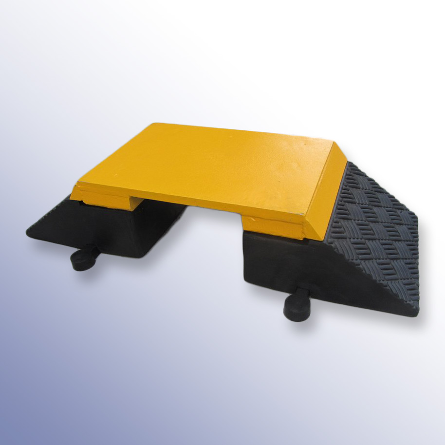
    High-visibility cable ramps are often the preferred choice in:Heavy Duty HGV Cable Ramp

    • Warehouses
    • Public spaces
    • Event venues
    • Construction sites
    • Emergency access routes

    The profile and positioning of the protector should also allow safe movement of pedestrians, wheelchairs, trolleys and vehicles wherever possible.

    Common Selection Mistakes to Avoid

    Some of the most common issues we encounter include:

    • Underestimating vehicle loads
    • Choosing channels that are too small
    • Using indoor products outdoors
    • Failing to consider installation duration
    • Selecting products with insufficient visibility

    Taking a few extra minutes to assess the environment and traffic requirements can significantly reduce the risk of accidents and premature product failure.

    Why Choose Polymax for Cable and Site Safety Solutions?

    At Polymax, we have experience helping customers across numerous industries, including manufacturing, warehousing, construction, utilities and live events.

    Whether you require a simple pedestrian cable cover for an exhibition stand or an 80-tonne-rated cable protector for a heavy-duty construction site, our team can help you identify the most suitable solution for your application.

    Many of our cable protectors and site safety products are available from stock and can be delivered quickly to help keep your project running safely and efficiently.

    Need Help Choosing the Right Cable Protector?

    By considering:

    • The environment
    • Traffic type and load requirements
    • Installation duration
    • Cable and hose size and capacity
    • Visibility and access requirements

    You can significantly improve site safety, protect valuable equipment and ensure compliance with health and safety obligations.

    If you're unsure which solution is right for your application, our team is always happy to help, contact us on +44(0) 1420 474 123 or E-mail us here.

  • What is Compression Set? Everything You Need to Know

    What is Compression Set?

    Compression set occurs when an elastomer undergoes permanent deformation and fails to fully recover its original shape after being subjected to prolonged compression. In sealing applications, this loss of elasticity can significantly reduce sealing performance and increase the risk of leakage.

    A common example is an O-ring that remains flattened after extended service. As the material loses its ability to rebound, the sealing force decreases, making compression set one of the leading causes of O-ring failure. Understanding what causes compression set and how to minimise it is essential when selecting seals for long-term reliability.

    How is Compression Set Measured?

    Compression set is a measure of an elastomer's ability to recover after being compressed for a specified period of time. It is commonly evaluated using the ASTM D395 testing standard, which measures the permanent deformation that remains after the compressive load has been removed.

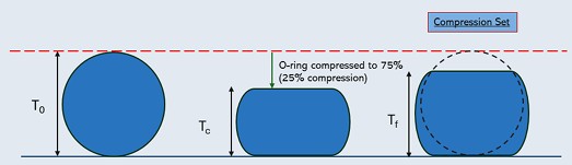
    During testing, the elastomer is compressed by a specified percentage, typically 25% of its original thickness for a defined period and temperature. Once the load is removed, the material is allowed to recover before its final thickness is measured.

    The result is expressed as the percentage of the original deformation that has not recovered. Lower compression set values indicate better elastic recovery and generally provide improved long-term sealing performance.

    Compression Set Formula for O-rings

    Showing the Compression set in O-rings

    Compression Set (%) = ((T₀ − Tᶠ) / (T₀ − Tc)) × 100 

    Where:

    • T₀ = Original O-ring cross-sectional thickness
    • Tᶠ = Final thickness after testing
    • Tc = Thickness under compression

    Causes of Compression Set

    Compression set can develop due to several factors, often acting together over time. Common causes include:

    Inadequate Heat Resistance

    Exposure to elevated temperatures can accelerate the breakdown of elastomer properties, reducing the material's ability to recover after compression. Selecting high-temperature materials such as FKM (Viton®) or silicone can help maintain elasticity in demanding environments.

    Poor Compression Set Performance

    Different elastomers exhibit varying resistance to permanent deformation. Materials with naturally lower compression set characteristics, such as EPDM and FKM, are often preferred for applications requiring long service life.

    Excessive O-ring Squeeze

    Applying too much compression during installation places additional stress on the elastomer and can accelerate permanent deformation. Recommended squeeze levels are typically:

    • Static seals: 15–30%
    • Dynamic seals: 8–16%

    Following established gland design guidelines helps optimise sealing performance while minimising compression set.

    Chemical Degradation

    Exposure to incompatible chemicals can alter the molecular structure of an elastomer, leading to hardening, softening, swelling, or permanent deformation. Ensuring material compatibility with the media being sealed is essential for long-term reliability.

    Factors Affecting Compression Set

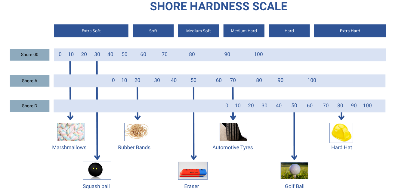
    Shore Hardness (ShA)

    Shore hardness influences how readily an elastomer deforms under load. Softer materials, such as 50 ShA silicone, generally compress more easily and may exhibit higher compression set values. Harder materials, such as 75 ShA FKM, tend to resist deformation more effectively and often provide improved compression set performance.

    Selecting the correct hardness helps balance sealing effectiveness, installation requirements, and long-term durability.

    O-ring Size

    Correct O-ring sizing plays an important role in maintaining seal integrity and reducing compression set. The cross-sectional thickness and gland dimensions determine the amount of squeeze applied during installation.

    Thicker O-rings may experience greater compression, increasing the risk of permanent deformation. Conversely, O-rings that are too thin may not generate sufficient sealing force. Oversized O-rings can also experience excessive installation stress, which may affect service life.

    Compression Set Performance of Common O-rings Materials

    Different elastomer compounds exhibit varying levels of compression set resistance. While application requirements such as temperature, chemical compatibility, and hardness should always be considered, the table below provides a general comparison of common O-ring materials and their typical compression set performance.

    Material Compression Set Resistance Temperature Resistance Typical Applications
    Silicone (VMQ) Fair Excellent Food processing, medical devices, high-temperature environments
    NBR (Nitrile) Good Good Hydraulic systems, fuel systems, oil sealing applications
    EPDM Very Good Excellent Water systems, steam applications, outdoor environments
    FKM (Viton®) Excellent Excellent Chemical processing, fuels, high-temperature sealing applications


    Why is Compression Set Important When Selecting an O-ring?

    O-rings function by maintaining continuous contact between the sealing surfaces and the gland. To achieve this, the elastomer is compressed during installation, creating the sealing force required to prevent leakage.

    Over time, heat, pressure, and chemical exposure can alter the polymer structure of the material. As elasticity decreases, the O-ring becomes less capable of returning to its original shape, reducing the sealing force available within the assembly.

    For this reason, compression set should be considered alongside chemical compatibility, temperature resistance, and hardness during material selection. Choosing an elastomer with good compression set resistance helps prevent premature seal failure, reduce maintenance costs, and improve long-term system reliability.

    In critical applications such as hydraulic systems, chemical processing equipment, and industrial machinery, compression set is often one of the most important indicators of long-term sealing performance.


    Need Help Call +44 (0)1420 474123 or e-mail us. We're here to help you find the perfect solution for reliable, long-lasting sealing.

  • 12 Years of Partnership, Quality and Progress: Polymax Recognised by EUSGA

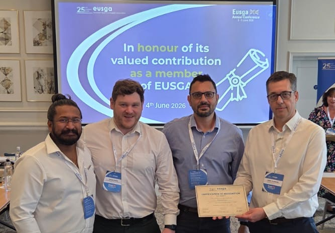
    The Polymax team was delighted to receive recognition at the recent annual conference of the European Sealing and Gasket Association (EUSGA), where we were presented with a certificate celebrating 12 years of membership.

    Being part of EUSGA reflects our ongoing commitment to quality, technical excellence, industry collaboration, and continuous improvement. For our customers, this means confidence in the products we supply, access to the latest industry knowledge, and a trusted partner dedicated to delivering reliable sealing solutions that meet the highest standards.

    We would like to thank EUSGA for this recognition and look forward to continuing to support our customers through innovation, expertise, and best practice across the industry.

5 Item(s)

Cookie Notice.
This websites use cookies. By continuing to browse the site you are agreeing to our use of cookies.